Ribbon
The Ribbon is located at the top of the main SDC Verifier window and contains the following pages:
Page "File"
This page contains the following commands: create, open, save a project and edit its properties, etc.
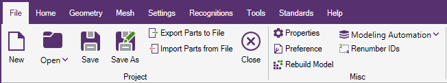
When SDC Verifier is started a project has to be created or opened.
New Project
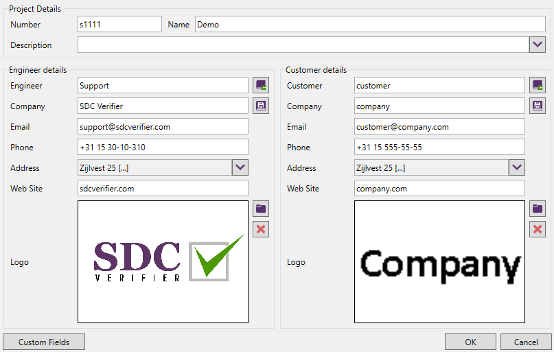
Create new SDC Verifier project:
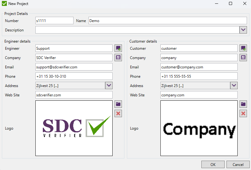
Project Details - a project number, report version and a project name;
Engineer details - a company and an engineer details who prepared this project;
Customer details - a company for whom the project is prepared;
Note: Engineer and Customer details are default settings for each new report.
 - save engineer/customer data to the library;
 - load engineer/customer data from the library.
Properties
Edit the opened project data:
All the settings are the same as described in New Project chapter.
:
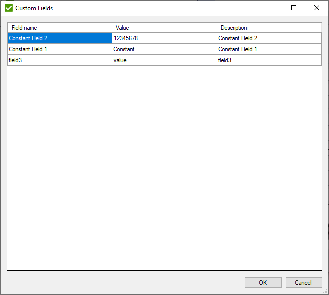
Custom fields are used in Report Layout.
Note: Custom field values are stored in the project file and can be different from project to project. Field names and descriptions are stored is settings and can be used between projects.
Open Project
To Open a project it is required to select the file with the extension *.sdcvp.
Note: Submenu of command contains a list of last 8 recently opened projects.
Import
Creates a new SDC Verifier project from current model or updates opened project with imported CAD geometry, finite elements model or analysis results.
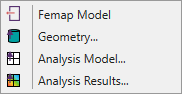
Femap Model - open and read items of existing finite element model created in Femap and create a new SDC Verifier project.
Model files("*.modfem"; "*.mod") or Neutral files ("*.neu") can be imported.
Geometry... - update opened SDC Verifier model by reading existing CAD geometry.
If SDC Verifier project is not opened a new one will be created.
Analysis Model... - read file with finite elements model to SDC Verifier project.
If SDC Verifier project is not opened a new one will be created.
Analysis Results... - read file with results of finite elements model analysis to SDC Verifier project.
If SDC Verifier project is not opened a new one will be created.
Save/Save as
Save the project to existing file or pick a custom file location (Save as).
Export Parts to File
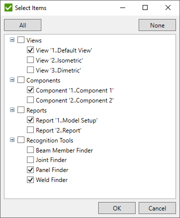
Export current project parts (Views, Components, Recognition Tools, Reports) to the file that can be imported in another project. Select the items from the list to be exported and select the location to save the file:
Import Parts from File
Import project parts (Views, Components, Recognition Tools, Reports) from the selected file that was created by Export Parts to File command.
Note: Project that uses different model from the one the information was exported should be checked manually as the ids of the items (e.g. elements, materials, loads) can be different and consequently some information can be mixed up or will not exist.
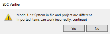
Note: Warning will be displayed if unit system stored in the file and unit system of current project are different. In this case dimensions in recognition tools will use the values in units stored in the file:
Project Preferences
Common settings of SDC Verifier that will be used for all projects.
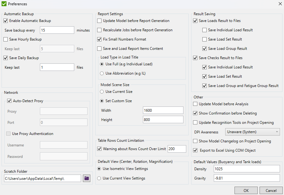
Automatic Backup
To prevent loosing of data in SDC Verifier use option Automatic Backup. It is possible to set the time intervals between the savings in minutes. By default, Automatic Backup is enabled and the time interval is 5 minutes.
If the project is saved, the backup file is stored in the project directory with the name "/Project Name/_backup type_/date_time/.sdcb". Where backup type is "auto backup", "backup" or "daily backup":
If SDC Verifier detects an unexpected exception, the file with the name "/Project Name/_restore.sdcb" will be created with the last project data.
Network
The Network options are recommended to be set only if the Internet connection is through Proxy Server and SDC Verifier fails to send the registration request or error reports.
Scratch Folder
The Scratch Folder option defines the location for storing temporary files during calculations.
Report Settings:
Update model before report generation - show notification to update the model information before the report generation.
Recalculate jobs before report generation - clear all results for Load Sets and Load Groups and recalculate them.
Fix Small Numbers Format - if a number is not zero, but after formatting display 0 then the number is shown in the scientific format.
Save and Load Report Items Content - keep Report Designer structure generated even after reopening the project. Option is used for all new Report Designers and can be overridden in the Report Settings of each Report Designer.
Load Type in Load Title - displays full type (e.g. Individual load) or abbreviation (e.g. IL) in a title of the load chapter.
Table rows count Limitation
If Warning about rows count over limit is selected a warning message for the tables with the row count more than the limitation count will be displayed. Generation of tables that do not match the condition will not be displayed in the report.
Default view (center, rotation, magnification)
Options are set for the default view when a new SDC Verifier project is created.
Use isometric view settings - rotation around X axis = 35.26439°; around Y = -45°; around Z = 0°. Center and magnification values are obtained after the model is auto scaled;
Use current view settings - rotation, center and magnification will be taken from the position of the model at the moment the new project is created;
Results saving
Select the type of results to be stored to the disk - load or check results by the selected load types.
Other
Update model before analysis - re-read information from the model;
Show confirmation before deleting - displays the message with a confirmation.
Update recognition tools on project opening - updates joints, beam members, welds, buckling plates if the model was modified since the last project's save;
DPI awareness - enable the different DPI scaling behavior;
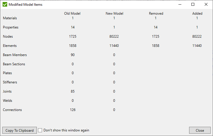
Show Model Changelog on Project Opening - displays window with an information of original and new items (elements, beam members etc.) count. Window is displayed after project opening and if the model was changed.
Export to Excel using COM object - create Excel file and open it. Requires installed MS Excel;
Default Values (Buoyancy and Tank loads)
Density and Gravity values (in model units) are used as default in Tank and Buoyancy loads.
Other Page "File" Commands
Rebuild Model - performs a full rebuild and compacts the model;
Modeling Automation
Parametric Model
Parametric model allows building a new Model by inputting the dimensions:
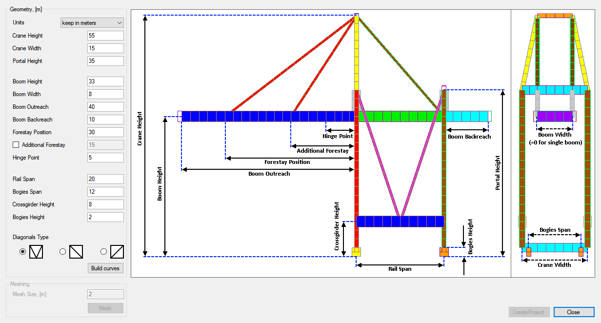
It is quick and easy to build a model of a new crane for personal or education purpose by changing only the necessary input. All the dimensions are shown on the picture.
Press to create a geometry and predefined material and properties of a crane. A new model will be created each time the button is pressed.
After the geometry is built set a Mesh Size and press the button to create FEM elements on the generated geometry.
Press to save the model to the file and start a new project in SDC Verifier.
File-to-Model
Allows create model with beam elements, properties, materials and geometry. Selected unit system will be set for a new project. For correct calculations, in *.xlsx files use values in the same unit system as selected for import.
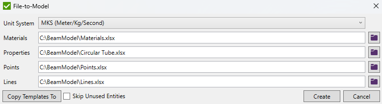
Press to select and copy templates to user defined destination folder:
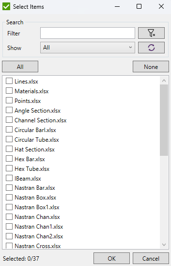
Skip Unused Entities - check to remove unused entities. For example, materials that are not used in any property, etc.
Press to generate a model.
File-to-Model Templates
There are 4 types of templates that are referenced by the following fields:
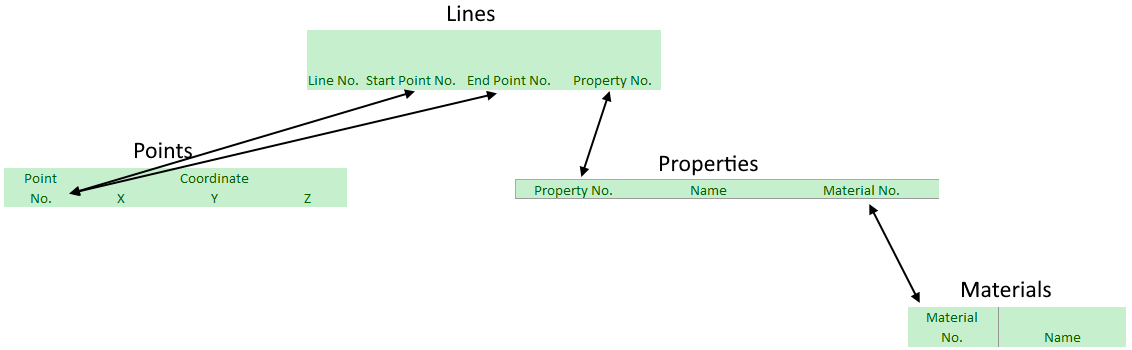
Materials Template
"Materials.xlsx" contains 8 fields to define for each material:
Material No. - material ID, Name, Young Modulus, Shear Modulus, Poisson Ratio, Density, Yield Stress, Tensile Strength.
Properties Templates
There are many templates for different shapes.
Shapes have fields that are common for all of them: Property No. - property ID, Name, Material No. - ID of material the property is linked with.
Area, Iyy, Izz, Izy, Torsional Constant, Y Shear Area, Z Shear Area, Nonstructural Mass Length, Warping Constant and Perimeter fields are optional.
All optional fields which are not set will be calculated automatically accroding to dimensional values of property.
Fields in columns after Perimeter column are dimensional values and are mandatory for setting as they are used to calculate some optional fields.
"Angle Section.xlsx"
Template for angle cross-section property:
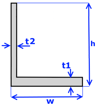
Dimensions: Height - h, Width - w, Thickness - t1, t2.
"Channel Section.xlsx"
Template for channel cross-section property:
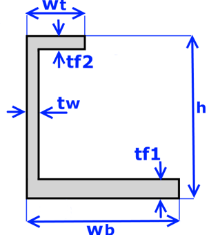
Dimensions: Height - h, W Top - Wt, W Bot - Wb, Thick Top - tf2, Thick Bot - tf1, Thick Web - tw.
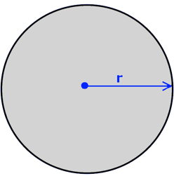
"Circular Barl.xlsx"
Template for circular bar property:
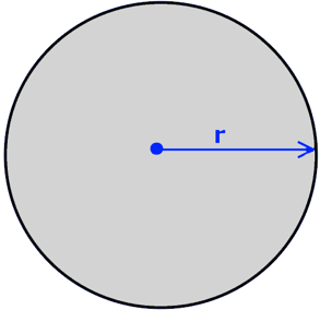
Dimensions: Radius - r.
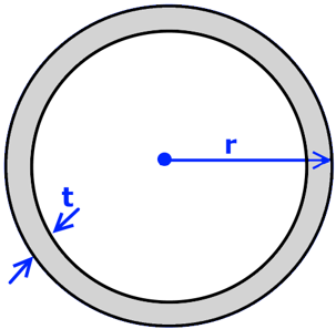
"Circular Tube.xlsx"
Template for circular tube property:
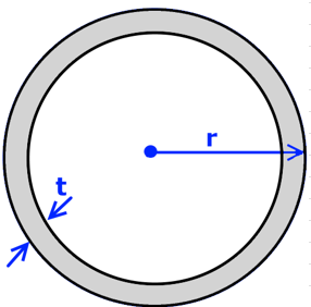
Dimensions: Radius - r, Thickness - t.
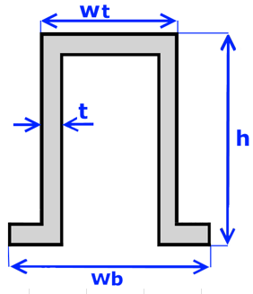
"Hat Section.xlsx"
Template for hat cross-section property:
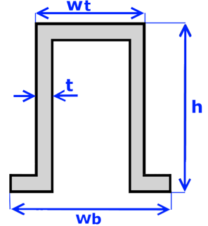
Dimensions: Height - h, W Top - Wt, W Bot - Wb, Thickness - t.
"Hex Bar.xlsx"
Template for hex bar property:
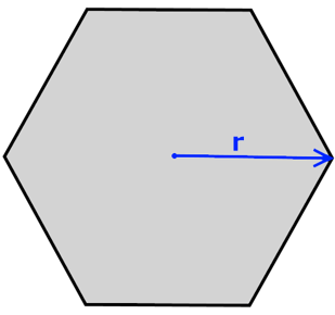
Dimensions: Radius - r.
"Hex Tube.xlsx"
Template for hex tube property:
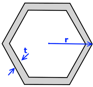
Dimensions: Radius - r, Thickness - t.
"IBeam.xlsx"
Template for I-shape cross-section property:
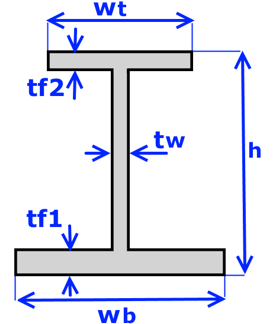
Dimensions: Height - h, W Top - Wt, W Bot - Wb, Thick Top - tf2, Thick Bot - tf1, Thick Web - tw
"Nastran Bar.xlsx"
Template for Nastran bar property:
Dimensions: Height - h, Width - w.
"Nastran Box.xlsx"
Template for Nastran box property:
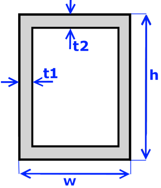
Dimensions: Height - h, Width - w, t2, t1.
"Nastran Box1.xlsx"
Template for Nastran box property:
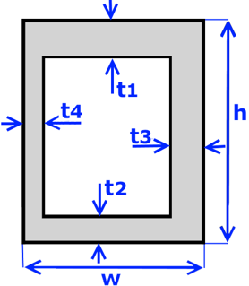
Dimensions: Height - h, Width - w, Thick Top - t1, Thick Bot - t2, Thick Right - t3, Thick Left - t4.
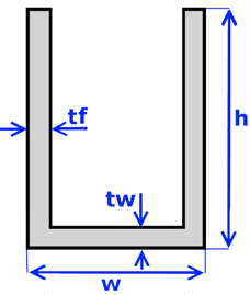
"Nastran Chan.xlsx"
Template for Nastran channel cross-section property:
Dimensions: Height - h, Width - w, Thick Bot - tf, Thickness - tw.
"Nastran Chan1.xlsx"
Template for Nastran channel cross-section property:
Dimensions: Height - h, Width - w, Thickness Flange - tf, Thickness Web - tw.
"Nastran Chan2.xlsx"
Template for Nastran channel cross-section property:
Dimensions: Height - h, Width - w, tw, tf.
"Nastran Cross.xlsx"
Template for Nastran cross cross-section property:
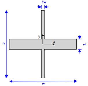
Dimensions: Height - h, Width - w, tw, tf.
"Nastran H Section.xlsx"
Template for Nastran H-shape cross-section property:
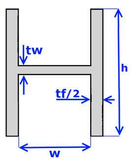
Dimensions: Height - h, Width - w, tf, tw.
"Nastran Hat.xlsx"
Template for Nastran hat cross-section property:
Dimensions: Height - h, Width Top - Wt, Width Bot - Wb, Thickness - t.
"Nastran Hat1.xlsx"
Template for Nastran hat cross-section property:
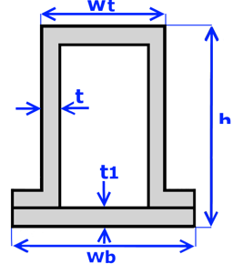
Dimensions: Height - h, Width Top - Wt, Width - Wb, t1, t.
"Nastran Hex.xlsx"
Template for Nastran hex cross-section property:
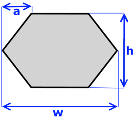
Dimensions: Height - h, a, Width - Wb.
"Nastran I Section.xlsx"
Template for Nastran I-shape cross-section property:
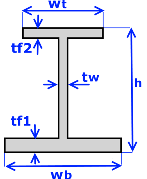
Dimensions: Height - h, W Top - Wt, W Bot - Wb, Thick Top - tf2, Thick Web - tw, Thick Bot - tf1.
"Nastran I1 Section.xlsx"
Template for Nastran I-shape cross-section property:
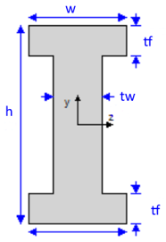
Dimensions: Height - h, Width - W, Thick Web - tw, Thick Flange - tf.
"Nastran L Section.xlsx"
Template for Nastran L-shape cross-section property:
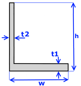
Dimensions: Height - h, Width - W, Thick Bot - t1, Thickness - t2.
"Nastran Rod Section.xlsx"
Template for Nastran rod property:
Dimensions: Radius - r.
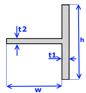
"Nastran T Section.xlsx"
Template for Nastran T-shape cross-section property:
Dimensions: Height - h, Width - W, t1, t2.
"Nastran T1 Section.xlsx"
Template for Nastran T-shape cross-section property:
Dimensions: Height - h, Width - W, t1, t2.
"Nastran T2 Section.xlsx"
Template for Nastran T-shape cross-section property:
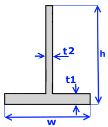
Dimensions: Height - h, Width - W, t1, t2.
"Nastran Tube Section.xlsx"
Template for Nastran tube property:
Dimensions: Radius - r, Thickness - t.
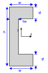
"Nastran Z Section.xlsx"
Template for Nastran Z-shape property:
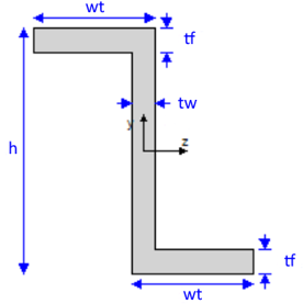
Dimensions: Height - h, wt, tf, tw.
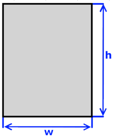
"Rectangular Bar.xlsx"
Template for rectangular bar property:
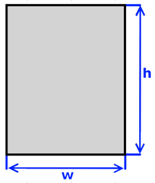
Dimensions: Height - h, Width - W.
"Rectangular Tube.xlsx"
Template for rectangular tube property:
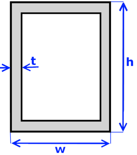
Dimensions: Height - h, Width - W, Thickness - t.
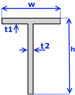
"T Shape.xlsx"
Template for T-shape cross-section property:
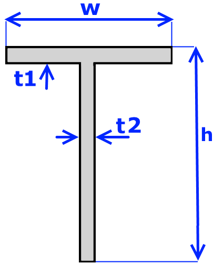
Dimensions: Height - h, W Top - W, Thick Top - t1, Thickness - t2.
"Trapezoidal Bar.xlsx"
Template for trapezoidal bar property:
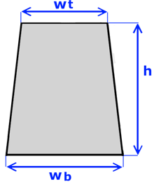
Dimensions: Height - h, W Top - Wt, W Bot - Wb.
"Trapezoidal Tube.xlsx"
Template for trapezoidal tube property:
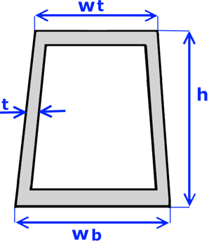
Dimensions: Height - h, W Top - Wt, W Bot - Wb, Thickness - t.
"Z Shape.xlsx"
Template for Z-shape property:
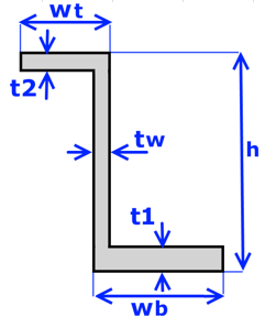
Dimensions: Height - h, wt, wb, t1, t2, tw.
Points Template
"Points.xlsx" contains 4 fields to define for each point:
Point No. - point ID, X, Y, Z - coordinates of point.
Lines Template
"Lines.xlsx" contains 4 fields to define for each line:
- Line No. - line ID;
- Start Point No. - Point No. (ID) of line`s start point;
- End Point No. - Point No. (ID) of line`s end point;
- Elements Count - count of elements on the line, preffered to use but not mandatory;
- Element Length - length of one element on the line(optional);
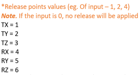
- Start Release - releases of start point of the line;
- End Release - releases of end point of the line;
- Rotation Angle - angle for rotation around X axis;
- Orientation Vector X - X component of elements orientation vector;
- Orientation Vector Y - Y component of elements orientation vector;
- Orientation Vector Z - Z component of elements orientation vector;
Start and End points releases can be set with values below:
Other Commands
- renumber Ids for all items in the project starting from ID = 1.
Renumbering the result items where the results can be stored to the files (jobs, loads, checks, standards) will lead to results clearing with a confirmation message since they are linked to the files by their IDs.
- unload the current SDC project and asks if the project has to be saved;
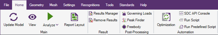
Page "Home"
This page contains the following commands:
- - synchronize model information (elements, properties etc.) with the project;
- View - add new View;
- - run analysis of active Job. Submenu contains commands to select a different job for analysis or Analyze Multiple jobs and standards to be calculated;
- Report Layout - allows customizing an appearance of the generated content;
- Results Manager - allows to operate with calculated by SDC Verifier results that are saved to files and choose the result folder location;
- Remove Results - remove results created by analysis in the model;
- Governing Loads - finds the critical (governing) loads from a large group of load combinations.
- Peak Finder - finds all peak zones based on the output results and presents them using a special plot and a summary table.
- Freebody - calculates a balanced set of forces/moments on a chosen part of a model.
- Optimization Tool - optimize structure design;
- SDC API - automate the process of interaction with SDC Verifier.
- - installs or runs a script prepared by support team to manage/fix specific requests on a software.
- - opens window to select a predefined script to be run.
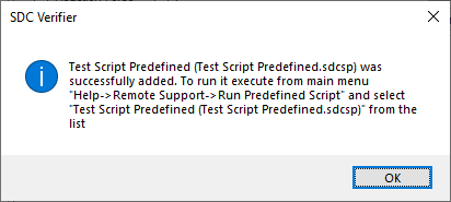
If script is predefined - it is required to install the script only once and it will be added to a list of predefined scripts and the message with the instructions how to run the script will appear:
If script is not predefined - to run the script it is necessary to select the script file each time.
Page "Geometry"
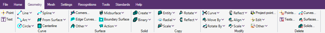
Containts commands to create, copy, modify and delete model geometry(points, curves, surfaces and solids).
More information about each command can be found here.
Page "Mesh"

Containts commands to create, copy, modify, delete and other actions with nodes and elements of the model.
More information about each command can be found here.
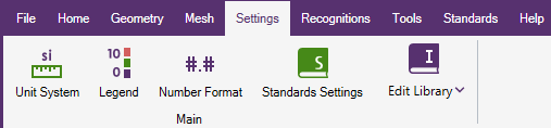
Page "Settings"
This menu contains:
- Unit System - used for the conversion units in check calculations;
- Legend Settings - define the legend style for different result categories;
- Number Formats - define the display style of numbers in the tables;
- Standards Settings - set Input values (Constants, Characteristics, Classifications) of the predefined standards;
- Edit Library - manage Standards, Wind, Number Format, Legend Settings and Shapes libraries.
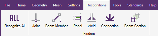
Page "Recognitions"
These menu commands are for model recognition:
- - run automatic recognition of all recognition tools;
- Joints Finder - recognize joints (1D, 2D, 3D, beam-plate and user joints);
- Beam Member Finder - recognize length in y, z and torsional directions;
- Beam Section Finder - group beam elements by planes XY, YZ, ZX and Custom;
- Panel Finder - recognize sections, plates, stiffeners and their dimensions automatically;
- Weld Finder - recognize welds on the model;
- Connection Finder - recognize beam-to-beam connections on the model;
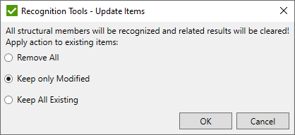
If any recognition tool contains recognized structural items - the window with the options to be applied for existing items will appear:
After the recognition process is finished, the window with the summary information will appear:
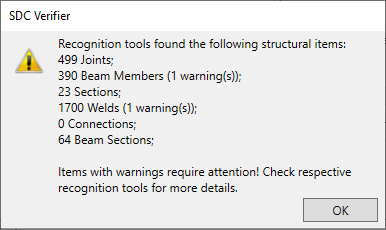
Recognition tools that require a manual intervention are marked with warnings in the round brackets.
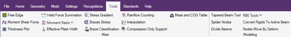
Page "Tools"
- Free Edge - automatically finds free edges between the elements
- Moment Shear Force - is for checking the validity of a ship;
- Interpolation - allows to display stress variation along the selected line between two mesh nodes;
- Weld Force Summation - is used to summarize Grid Point Forces over welds recognized by Weld Finder. The results of the tool are used in Weld Checks;
- Moment Ratio - calculates the moment ratio on the ends of the member found by Beam Member Finder;
- Effective Plate Width - calculates plate effective width for stiffeners recognized in Panel Finder;
- Stress Gradient - calculates related stress gradient coefficients;
- Braces Stress - calculate axial, in-plane and out-of-plane bending stresses for braces recognized in Connection Finder;
- Braces Classification - calculate percentage of brace classification (K, TY, Cross) in the connections recognized in Connection Finder depending on what load is applied;
- Rainflow Counting - determine the number of fatigue cycles presented in a load-time history;
- Mass and COG Table - mass and center of the gravity table;
- Compression Only Support - simulation of compression only support by creating dependency loads and modifying Load Sets to reach 0 reaction at the support nodes;
- Thickness Plot - the plot with properties thicknesses using the text labels;
- Tapered Beam Tool - refine mesh of tapered beams and create new properties in the model;
- Spider Nodes - creates a Rigid (RBE2) element by establishing an independent node at the centroid of user-selected nodes. The selected nodes serve as the dependent nodes for the Rigid element;
- Divide Beams - divides a single selected beam element into the specified number of elements. The original element's start and end nodes remain in their respective positions;
- Convert RBE2s to RBE3s - changes selected RBE2 elements to RBE3 elements. It keeps any rotational movement from the independent nodes that used to be connected to the RBE2 elements;
- Convert Rigids to Active Beam - turns selected rigid elements into the active beam property ID;
- Separate colors (RBE2s, RBE3s) - sets one color for all RBE2 and a single different color for all RBE3 elements in the model.
- Nodes Move by Deform - moves nodes by the value of the X, Y, and Z deformation values of the active Output Set.
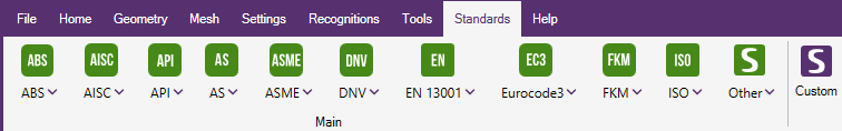
Page "Standards"
Add predefined or custom standards. List of available predefined standards is described in the Standards chapter.
Page "Help"
Contains commands to open help topics, request a license etc.
- - Opens an online help on Get Started chapter;
- - visit SDC Verifier website;
- - open a page with available tutorials at SDC Verifier website;
- - open SDC Verifier YouTube channel with list of demos/webinars;
- - manage the license or request it. For more detailed information see Licensing;
- - full information about the amount of licenses and licensed modules;
- - open the file that contains detailed information about errors. It is recommended to send this file and the error description to support@sdcverifier.com
- - open a directory where the log file is located;
- - Check if a new version is available:
- - checks on messages or important information from SDC Verifier. Messages are displayed at the bottom right pop up window. Critical messages are shown in the separate window;
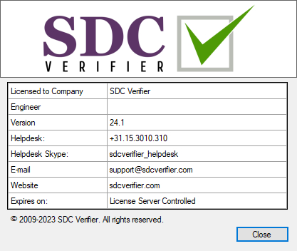
- - dialog with SDC Verifier information: